Categories
Equipment

Image annotation

One of the tasks that you might want to do with an image is to identify and annotate the objects within it. With it’s ImageSolver and AnnotateImage scripts PixInsight makes this really easy. The AnnotateImage script comes with several pre-canned catalogs such as Named Stars, Messier, NGC and PGC catalogs but also gives you the ability to specify your own. What I’m going to describe here is how to generate and use your own catalog from a VizieR source.

As I’m interested in Dark Nebulae, for this example I’m going to use the Lynds Dark Nebulae catalog and the first step will be to download it from VizieR. First we have to identify the catalog so we visit the search site http://cdsarc.u-strasbg.fr/viz-bin/Cat

Entering the authors name (Lynds, in this example) returns a list of all matching catalogs. We need the second item in the list which has a catalog ID of VII/7A/ldn. Clicking on the title, Lynds’ Catalogue of Dark Nebulae (LDN) (Lynds 1962), takes us to the catalog selection page http://vizier.u-strasbg.fr/viz-bin/VizieR?-source=VII%2F7A.

We could also search on any other identifying information or, if you’re unsure you can browse the entire collection.

We’re going to use a simple constraint query to return all catalog entries but with just the selection of fields that we require. There’s a lot of flexibility here and you can filter records based upon various criteria such as object size or magnitude to limit the search but we’re going to keep it simple here. The fields we require are LDN and Area so ensure that these columns are ticked and clear all the others. We don’t select the columns for RA and DEC as these are of the wrong epoch and also incorrectly formatted and there’s an easier way to obtain the correct information. On the left of the screen is a Preferences panel with more options; select Compute and tick the J2000 box. This will return correctly formatted, J2000 coordinates which will save us some work later.

Also select ‘ascii text/plain’ from the drop down list and select Decimal for ‘Position in’. Choose a value for Max that matches what you expect in terms of the number of catalog entries. Finally, we’re ready to Submit the query and the results will be returned on the next page.

Make a note of the column headers and then copy and paste all of the catalog entries into a text file on your computer. Next, fire up your favourite spreadsheet program and import the text file such that the data is divided into discreet columns and correctly aligned. I’m not going to describe exactly how to manipulate the data in your spreadsheet; just the general objectives so that the data is correctly formatted.

The AnnotateImage script can work with the following columns:

  • NAME – An object label (optional)
  • RA – Object coordinates in degrees (not hours) format (required)
  • DEC – Object coordinates in degrees format (required)
  • DIAMETER – Object size, in arc minutes. If this is not specified, a point source is assumed (optional)
  • MAGNITUDE – Object brightness (optional)

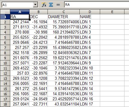
Put these column names, as required, into the first line of the spreadsheet.

Next, perform any required data manipulation on the object information. In this example, I amended the Name column to include the LDN prefix on each entry and also recalculated the Area values as diameters. Once this is done, save the spreadsheet as a tab delimited text file. The result looks something like this:

Spreadsheet

Now we’re ready for PixInsight. Load your linear image and run the ImageSolver script, entering values and parameters as required in order to plate solve the image. Documentation is available either online or in the program for this and once it’s completed successfully you can progress with any image processing that’s required to form your final image. Note that, once solved, you cannot resize or resample the image so carry out these tasks first.

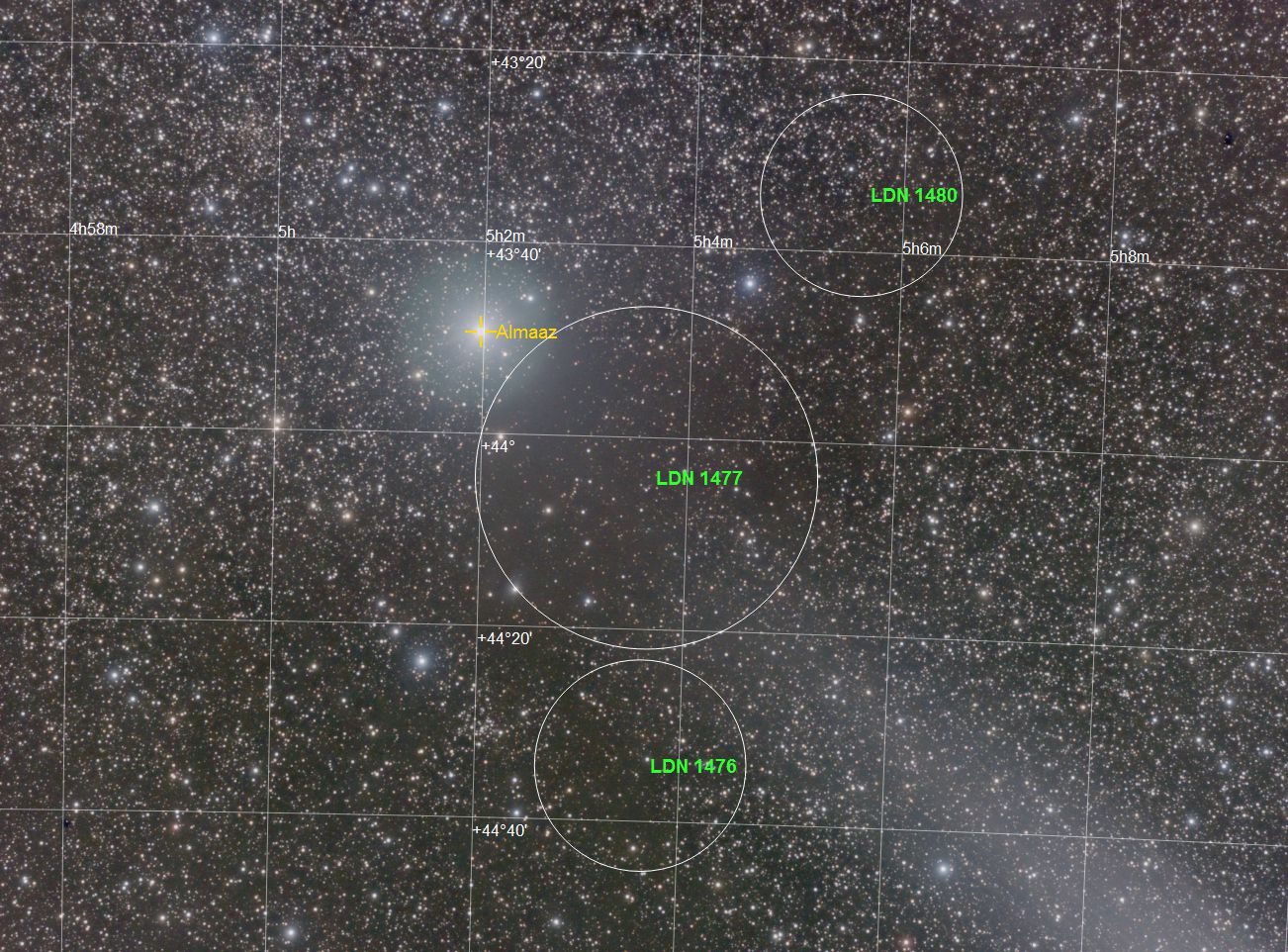
Run the AnnotateImage script, select any of the predefined catalogs required, click the + button and add a custom catalog, supplying the path to the previously saved text file in the dialog box. You should now have a new image with all the objects identified and marked.

LDN1477_DBE_Annotated

Categories
Equipment

Setting up a Pulsar Dome (Pt 2)

In part 1 we looked at getting a Pulsar dome to follow movements of the telescope when slewing from within Cartes Du Ciel. This time we’ll build on this foundation and add Maxim DL to the mix.
Recall from part 1 that both EQAscom and Shelyak dome driver have only POTH connected to them. POTH intercepts mount movements and calculates dome movements to match. This is required as the planetarium does not have the ability to connect to a dome.
Maxim DL does have the ability to directly control a dome so by connecting it’s dome output to POTH we can control the dome either via Maxim or the planetarium. POTH acts as a hub enabling us to connect more than one program to a single device. The telescope device EQAscom also acts as a hub and multiple programs can be connected to it, however, by connecting Maxim to POTH we can ensure that the system waits for the dome to finish it’s slew after any telescope move.
All of the dome slaving measurements that we made previously have to be entered in Maxim as well from the Options button on the dome tab of the observatory window. The setup screen specifies inches as the unit of measurement but this is not important provided the same unit is used for all values within this screen. Don’t forget that the dome size is specified here as the radius and not diameter.
The telescope type should be set manually as German Equatorial and the pier side as ASCOM Normal. These setting are available from the observatory setup tab’s Options button.
The dome home azimuth can be set but leave the sync option unticked as the driver will do this for us.
And that’s it! Additional programs can be connected provided you follow the same rules as we’ve adopted here for Cartes Du Ciel and Maxim. If you’ve entered all of the measurements and the home azimuth position accurately then the dome should follow the telescope as it slews and tracks around the sky driven from both Maxim and your planetarium program.

Categories
Equipment

Setting up a Pulsar dome

Having recently worked through the issues of slaving a Pulsar dome to a telescope and helping someone else through the same process I thought it would be useful to document the setup here.  I have an Avalon Linear Fast Reverse mount but from a software point of view this is identical to an EQ6 and I use Maxim DL for image capture, CCD Commander for automation and Cartes Du Ciel as a planetarium. With a few peculiarities, the setup is applicable to other programs that you may be using.

The first step is to run the Shelyak Test_DomeTracker.exe program. This is supplied on the CD and you’ll need to run ‘Do Calibration’ several times. What you’re looking for is that the number of steps per rotation remains very similar from run to run. Any large differences here means that mechanical problems are causing you to lose steps. This must be rectified before continuing. Make a note of the number of steps per rev and acc/decc steps obtained.

Next up we need to run POTH which is available in Scope-Dome hubs under the Ascom Platform 6 program group. We need POTH because we can only connect one program to the Shelyak ASCOM driver. With POTH, we connect it to the dome driver and then connect our other programs to POTH. There’s a fair amount of information to add to the dome setup screen and it will require some careful measurements of your mount and pier and it’s position within your dome. Within POTH, click Setup. If dome data isn’t displayed then press Dome>> to expand the screen.

Click ‘Choose Dome’, select the Shelyak ASCOM dome driver and click Properties.

Capture1Enter your COM serial number, then look at the Dome Azimuth settings. Enter the values you obtained from your calibration runs, your best guess for the home azimuth position and the dome diameter (in metres). Now we need some measurements from your dome and mount so a tape measure will be required.

All measurements are made from an imaginary point at the intersection of RA and DEC axis on your mount. This will be inside the body but make an estimate of it’s position. From this point make the following measurements:

  1. Any East-West offset referenced to the dome. Usually this is zero but check to make sure
  2. Any North-South offset, again referenced to the dome. If there’s any offset, it will usually be to the south so this will be entered as a negative number
  3. The height of the intersection above or below the base of the dome hemisphere

All these measurements are made in metres and are entered in the relevant dialog boxes under ‘Telescope position wrt dome’.

You’ll need one more measurement; the distance between the intersection and the optical axis of your telescope. Don’t forget that a top mounted guide scope will significantly increase this distance. This is entered as the German mount offset and you’ll also have to set the mount management here as per the illustration above. Click the OK button

Once all this information is entered you’re most of the way there. Now we check the home position azimuth that you entered.

Start the test_ASCOM_DomeTracker.exe program from the CD, check the Setup dialog to ensure the information you entered is all correct and then Connect.

Capture2

Park the mount so it’s pointing due north and using the Actions buttons in the program ‘Find Home’. The dome should move to it’s home position with the silver tape in front of the sensor. Next Slew to AZ 0 degrees and the dome slit should end up directly in front of the telescope. Failure at this point indicates that either your tick count or home position is incorrect. As you’ve carefully made multiple calibration runs earlier we’ll assume it’s the home position. Using the setup dialog, make an adjustment to the home azimuth setting and re-home the dome. Slew to AZ zero again and compare the dome position to the previous position. Repeat this process until the dome slit stops reliably in front of the telescope when slewed.

It’s worth stressing here that you must get the previous stage setup and working reliably before moving on. The dome must reliably move from the Home position to North otherwise what follows will be an exercise in frustration.

With all this done the dome should be set and it’s time to bring the mount into play. Once again, like the dome, we will connect POTH to the ASCOM mount driver and then connect other programs to POTH. The reason for this is that POTH will intercept mount moves for us and command the dome to move as well to follow the telescope pointing. Using the POTH setup screen choose the EQ6 driver, setup and then connect. The screen should look similar to this:

Capture3

Note that you need to enter your mount/dome measurements again in the Geometry section. Pay attention here as this time the dome radius is required in metres and all other measurements are in millimetres.

In your planetarium program (for this example we’ll be using Cartes Du Ciel) open the telescope dialog and select the POTH.Telescope driver.

Capture4Once you’ve pressed the Connect button, slews initiated within the planetarium will move both the telescope and the dome in sync.

In Part 2 I’ll look at connecting Maxim.

Categories
Equipment Galaxy Nebula

Work in progress…

Having got the backend of the 60mm finder swapped for a guider adapter the next job was to sort an EQdir replacement for the SynScan hand controller. Initially I thought I’d use an FTDI serial-TTL cable but I’m short of USB sockets on the Asus Netbook and I want to connect my bluetooth GPS receiver as well so I went looking for a wireless solution. Hobbytronics sell a suitable bluetooth module and I found some example circuit diagrams on the EQmod website so set to work with a soldering iron. Here’s the end result, prior to boxing up:
EQDIR
Testing revealed no problems so I put it in a small plastic project box and it hangs off the mount’s DB-9 connector.
The next problem was some star elongation I noticed when imaging NGC4244 on friday night. Initially I thought it was field rotation, but a closer look showed that the elongation was in the RA direction. While the guide log showed both axis having less than 0.5 pixel errors, RA was considerably worse and was bouncing between +/- errors. Next time out, I reduced the aggressiveness of the RA guide corrections and with a setting of 0.4 the problem was much reduced. As I previously mentioned, I’ve got a sizeable unbalance in the RA axis while I wait for a replacement counterweight so hopefully, this is the root cause of the problem.
Here’s the result of the tuning. 13 frames of 5 minutes each of M97 & M108 in Ursa Major.
M108
Telescope: Zenithstar 70
Camera: QHY9C

Categories
Equipment

New mount

Here’s a picture of my new setup. My bank balance is lighter, and Italy’s trade balance has improved significantly!

Operationally, the Avalon Linear Fast Reverse is an EQ6. The interesting bit is that the EQ6’s worm gear has been replaced by a belt & pulley reduction drive. The manufacturer claims very accurate guiding is possible using this system. The mount is controlled using either a Synscan hand control or EQMod on the computer. As the bits to make a direct computer connection haven’t arrived I’m using the handset in pass-through mode.

I haven’t got the backend for my 60mm finder scope guider yet so I’ve got my QHY5 attached to a Canon 75-300 lens via a Geoptik adapter. I’ll need to source a lighter counterweight as the 3Kg is too much for the Zenithstar.

_MG_8202